ubuntu20.04 bond0网口聚合配置
sudo apt update
sudo apt install ifenslave
vim /etc/modules
bonding mode=0 arp_interval=100 fail_over_mac=1 updelay=100
物理网口直连
服务器1
# This is the network config written by 'subiquity'
network:
ethernets:
eno1:
dhcp4: false
addresses:
- 192.168.254.77/22
optional: true
routes:
- to: default
via: 192.168.255.2
nameservers:
addresses:
- 8.8.8.8
- 114.114.114.114
enp11s0f0:
dhcp4: false
# addresses: []
optional: true
enp11s0f1:
dhcp4: false
# addresses: []
optional: true
enp11s0f2:
dhcp4: false
optional: true
enp11s0f3:
dhcp4: false
optional: true
version: 2
bonds:
bond0:
dhcp4: false
addresses:
- 10.0.11.77/24
interfaces:
- enp11s0f0
- enp11s0f1
parameters:
mode: balance-rr
#primary: enp11s0f0
mii-monitor-interval: 100
lacp-rate: fast
transmit-hash-policy: layer2
服务器2
# This is the network config written by 'subiquity'
network:
ethernets:
eno1:
dhcp4: false
addresses:
- 192.168.254.79/22
optional: true
routes:
- to: default
via: 192.168.255.2
nameservers:
addresses:
- 114.114.114.114
- 8.8.8.8
enp8s0f0:
dhcp4: false
optional: true
enp8s0f1:
dhcp4: false
optional: true
enp8s0f2:
dhcp4: false
optional: true
enp8s0f3:
dhcp4: false
optional: true
version: 2
bonds:
bond0:
dhcp4: false
addresses:
- 10.0.11.79/24
interfaces:
- enp8s0f0
- enp8s0f1
parameters:
mode: balance-rr
mii-monitor-interval: 100
lacp-rate: fast
transmit-hash-policy: layer2
nohup modprobe -r bonding && modprobe bonding && netplan apply &
#防止断网
cat /proc/net/bonding/bond0
网口:
ethtool bond0
Settings for bond0:
Supported ports: [ ]
Supported link modes: Not reported
Supported pause frame use: No
Supports auto-negotiation: No
Supported FEC modes: Not reported
Advertised link modes: Not reported
Advertised pause frame use: No
Advertised auto-negotiation: No
Advertised FEC modes: Not reported
Speed: 20000Mb/s
Duplex: Full
Auto-negotiation: off
Port: Other
PHYAD: 0
Transceiver: internal
netlink error: Operation not permitted
Link detected: yes
华为交换机配置:
堆叠
设备组建堆叠示例(通过业务口普通线缆)
组网需求
在一个新建的企业网络中,要求接入设备具有充足的端口数目,并且希望网络结构简单,易于配置和管理。
如图1所示,根据用户需求,SwitchA、SwitchB和SwitchC三台接入交换机采用环形堆叠组网,并通过跨设备Eth-Trunk连接上层设备SwitchD。其中,SwitchA、SwitchB和SwitchC的角色分别为主、备、从,堆叠ID分别为0、1、2,优先级分别为200、100、100。由于组成堆叠的成员交换机在逻辑上是一个整体,所以整个网络在扩展了端口数量的同时也方便了用户对网络的管理和维护。
组网以S5720-LI交换机为例。

配置思路
- 为了能够在堆叠的成员交换机之间转发数据报文,需要配置逻辑堆叠端口,并添加物理成员端口。
- 为方便用户管理,配置成员交换机的堆叠ID和优先级。
- SwitchA、SwitchB、SwitchC下电。按照图1所示,使用SFP+堆叠电缆连接各物理成员端口后再上电。
- 为提高可靠性、增加上行链路带宽,配置跨设备Eth-Trunk。

本端设备逻辑堆叠端口stack-port n/1里的物理成员端口只能与对端设备逻辑堆叠端口stack-port m/2里的物理成员端口相连。
如果SwitchA、SwitchB、SwitchC设备款型不完全一致,也必须使用可以混堆的设备款型。设备是否可以混堆,请参见堆叠配置注意事项中的描述。
组建堆叠时,最终生效的软件版本是竞争为主交换机的设备使用的软件版本。备交换机和从交换机会自动同步主交换机的软件版本。
操作步骤
- 配置逻辑堆叠端口并加入物理成员端口# 配置SwitchA的业务口GigabitEthernet0/0/27、GigabitEthernet0/0/28为物理成员端口,并加入到相应的逻辑堆叠端口。
<FutureMatrix> system-view
[FutureMatrix] sysname SwitchA
[SwitchA] interface stack-port 0/1
[SwitchA-stack-port0/1] port interface gigabitethernet 0/0/27 enable
Warning: Enabling stack function may cause configuration loss on the interface. Continue? [Y/N]:y
Info: This operation may take a few seconds. Please wait.
[SwitchA-stack-port0/1] quit
[SwitchA] interface stack-port 0/2
[SwitchA-stack-port0/2] port interface gigabitethernet 0/0/28 enable
Warning: Enabling stack function may cause configuration loss on the interface. Continue? [Y/N]:y
Info: This operation may take a few seconds. Please wait.
[SwitchA-stack-port0/2] quit
# 配置SwitchB的业务口GigabitEthernet0/0/27、GigabitEthernet0/0/28为物理成员端口,并加入到相应的逻辑堆叠端口。
<FutureMatrix> system-view
[FutureMatrix] sysname SwitchB
[SwitchB] interface stack-port 0/1
[SwitchB-stack-port0/1] port interface gigabitethernet 0/0/27 enable
Warning: Enabling stack function may cause configuration loss on the interface. Continue? [Y/N]:y
Info: This operation may take a few seconds. Please wait.
[SwitchB-stack-port0/1] quit
[SwitchB] interface stack-port 0/2
[SwitchB-stack-port0/2] port interface gigabitethernet 0/0/28 enable
Warning: Enabling stack function may cause configuration loss on the interface. Continue? [Y/N]:y
Info: This operation may take a few seconds. Please wait.
[SwitchB-stack-port0/2] quit
# 配置SwitchC的业务口GigabitEthernet0/0/27、GigabitEthernet0/0/28为物理成员端口,并加入到相应的逻辑堆叠端口。
<FutureMatrix> system-view
[FutureMatrix] sysname SwitchC
[SwitchC] interface stack-port 0/1
[SwitchC-stack-port0/1] port interface gigabitethernet 0/0/27 enable
Warning: Enabling stack function may cause configuration loss on the interface. Continue? [Y/N]:y
Info: This operation may take a few seconds. Please wait.
[SwitchC-stack-port0/1] quit
[SwitchC] interface stack-port 0/2
[SwitchC-stack-port0/2] port interface gigabitethernet 0/0/28 enable
Warning: Enabling stack function may cause configuration loss on the interface. Continue? [Y/N]:y
Info: This operation may take a few seconds. Please wait.
[SwitchC-stack-port0/2] quit
- 配置堆叠ID和堆叠优先级# 配置SwitchA的堆叠优先级为200。
[SwitchA] stack slot 0 priority 200
Warning: Do not frequently modify the Priority because it will make the stack split. Continue? [Y/N]:y
# 配置SwitchB的堆叠ID为1。
[SwitchB] stack slot 0 renumber 1
Warning: All the configurations related to the slot ID will be lost after the slot ID is modified.
Do not frequently modify the slot ID because it will make the stack split. Continue? [Y/N]:y
Info: Stack configuration has been changed, and the device needs to restart to make the configuration effective.
# 配置SwitchC的堆叠ID为2。
[SwitchC] stack slot 0 renumber 2 Warning: All the configurations related to the slot ID will be lost after the slot ID is modified. Do not frequently modify the slot ID because it will make the stack split. Continue? [Y/N]:y Info: Stack configuration has been changed, and the device needs to restart to make the configuration effective. - SwitchA、SwitchB、SwitchC下电,使用SFP+电缆连接后再上电。
- 下电前,建议通过命令save保存配置。
- 本设备的stack-port 0/1必须连接邻设备的stack-port 0/2,否则堆叠组建不成功。
- 为保证堆叠组建成功,建议按照以下顺序进行连线上电(如果用户希望某台交换机为主交换机可以先为其上电。例如,按以下顺序连线上电后,SwitchA为主交换机):
- 为SwitchA、SwitchB、SwitchC下电;
- 连接SwitchA与SwitchB之间的堆叠线缆;
- 先为SwitchA上电,SwitchA启动后,再为SwitchB上电;
- 检查SwitchA与SwitchB的堆叠组建是否成功,详细检查方法可参见检查堆叠组建是否成功;
- 与上一步类似:连接SwitchC与SwitchB和SwitchA之间的堆叠线缆,再为SwitchC上电;
- 检查SwitchA、SwitchB、SwitchC的堆叠组建是否成功,详细检查方法可参见检查堆叠组建是否成功。
- 配置跨设备Eth-Trunk在堆叠系统上行链路上配置跨设备Eth-Trunk,具体配置过程请参见配置堆叠Eth-Trunk示例。
- 验证配置结果# 查看堆叠系统的基本信息。
[SwitchA] display stack
Stack mode: Service-port
Stack topology type : Ring
Stack system MAC: xxxx-xxxx-xxx5
MAC switch delay time: 10 min
Stack reserved vlan : 4093
Slot of the active management port: --
Slot     Role        Mac address      Priority   Device type
-------------------------------------------------------------
    0     Master      xxxx-xxxx-xxx5   200        S5720-28P-LI-AC
    1     Standby     xxxx-xxxx-xxx4   100        S5720-28P-LI-AC
    2     Slave       xxxx-xxxx-xxx1   100        S5720-28P-LI-AC
 Feedback
端口聚合:
配置手工模式链路聚合示例(交换机之间直连)
组网图形

组网需求
如图1所示,SwitchA和SwitchB通过以太链路分别都连接VLAN10和VLAN20的网络,且SwitchA和SwitchB之间有较大的数据流量。
用户希望SwitchA和SwitchB之间能够提供较大的链路带宽来使相同VLAN间互相通信。同时用户也希望能够提供一定的冗余度,保证数据传输和链路的可靠性。
配置思路
采用如下的思路配置负载分担链路聚合:
-
创建Eth-Trunk接口并加入成员接口,实现增加链路带宽。
-
创建VLAN并将接口加入VLAN。
-
配置负载分担方式,实现流量在Eth-Trunk各成员接口间的负载分担,增加可靠性。
操作步骤
- 在SwitchA和SwitchB上创建Eth-Trunk接口并加入成员接口。
<HUAWEI> system-view
[HUAWEI] sysname SwitchA
[SwitchA] interface eth-trunk 1
[SwitchA-Eth-Trunk1] trunkport gigabitethernet 0/0/1 to 0/0/3
[SwitchA-Eth-Trunk1] quit
<HUAWEI> system-view
[HUAWEI] sysname SwitchB
[SwitchB] interface eth-trunk 1
[SwitchB-Eth-Trunk1] trunkport gigabitethernet 0/0/1 to 0/0/3
[SwitchB-Eth-Trunk1] quit
- 创建VLAN并将接口加入VLAN。
# 创建VLAN10和VLAN20并分别加入接口。SwitchB的配置与SwitchA类似,不再赘述。
[SwitchA] vlan batch 10 20
[SwitchA] interface gigabitethernet 0/0/4
[SwitchA-GigabitEthernet0/0/4] port link-type trunk
[SwitchA-GigabitEthernet0/0/4] port trunk allow-pass vlan 10
[SwitchA-GigabitEthernet0/0/4] quit
[SwitchA] interface gigabitethernet 0/0/5
[SwitchA-GigabitEthernet0/0/5] port link-type trunk
[SwitchA-GigabitEthernet0/0/5] port trunk allow-pass vlan 20
[SwitchA-GigabitEthernet0/0/5] quit
# 配置Eth-Trunk1接口允许VLAN10和VLAN20通过。SwitchB的配置与SwitchA类似,不再赘述。
[SwitchA] interface eth-trunk 1
[SwitchA-Eth-Trunk1] port link-type trunk
[SwitchA-Eth-Trunk1] port trunk allow-pass vlan 10 20
[SwitchA-Eth-Trunk1] quit
- 配置Eth-Trunk1的负载分担方式。SwitchB的配置与SwitchA类似,不再赘述。
[SwitchA] interface eth-trunk 1
[SwitchA-Eth-Trunk1] load-balance src-dst-mac
[SwitchA-Eth-Trunk1] quit
- 验证配置结果
在任意视图下执行display eth-trunk 1命令,检查Eth-Trunk是否创建成功,及成员接口是否正确加入。
[SwitchA] display eth-trunk 1
Eth-Trunk1's state information is:
WorkingMode: NORMAL           Hash arithmetic: According to SA-XOR-DA
Least Active-linknumber: 1     Max Bandwidth-affected-linknumber: 8
Operate status: up             Number Of Up Port In Trunk: 3
--------------------------------------------------------------------------------
PortName                           Status       Weight
GigabitEthernet0/0/1               Up           1
GigabitEthernet0/0/2               Up           1
GigabitEthernet0/0/3               Up           1
从以上信息看出Eth-Trunk 1中包含3个成员接口GigabitEthernet0/0/1、GigabitEthernet0/0/2和GigabitEthernet0/0/3,成员接口的状态都为Up。Eth-Trunk 1的“Operate status”为Up。
配置文件
-
SwitchA的配置文件
#
sysname SwitchA
#
vlan batch 10 20
#
interface Eth-Trunk1
 port link-type trunk
 port trunk allow-pass vlan 10 20
 load-balance src-dst-mac
#
interface GigabitEthernet0/0/1
 eth-trunk 1
#
interface GigabitEthernet0/0/2
 eth-trunk 1
#
interface GigabitEthernet0/0/3
 eth-trunk 1
#
interface GigabitEthernet0/0/4
 port link-type trunk
 port trunk allow-pass vlan 10
#
interface GigabitEthernet0/0/5
 port link-type trunk
 port trunk allow-pass vlan 20
#
return
-
SwitchB的配置文件
#
sysname SwitchB
#
vlan batch 10 20
#
interface Eth-Trunk1
 port link-type trunk
 port trunk allow-pass vlan 10 20
 load-balance src-dst-mac
#
interface GigabitEthernet0/0/1
 eth-trunk 1
#
interface GigabitEthernet0/0/2
 eth-trunk 1
#
interface GigabitEthernet0/0/3
 eth-trunk 1
#
interface GigabitEthernet0/0/4
 port link-type trunk
 port trunk allow-pass vlan 10
#
interface GigabitEthernet0/0/5
 port link-type trunk
 port trunk allow-pass vlan 20
#
return
查看现有堆叠信息:
display device //查看堆叠系统中各成员交换机的个数与实际组网中交换机的个数是否一致
display stack //查看堆叠系统的连接拓扑
display stack peers //查看堆叠系统的邻居信息
display stack port //查看与逻辑堆叠端口绑定的物理成员端口的信息。
display stack channel all //查看堆叠链路的连线及状态信息
————————————————
版权声明:本文为CSDN博主「Richardlygo」的原创文章,遵循CC 4.0 BY-SA版权协议,转载请附上原文出处链接及本声明。
原文链接:https://blog.csdn.net/Richardlygo/article/details/125876082
现网堆叠系统新加入成员交换机示例(业务口普通线缆堆叠)


配置思路
- 分析原堆叠的物理连接,选择新成员设备的加入点。
- 在SwitchE上进行业务口堆叠的相关软件配置:需要配置逻辑堆叠端口,并添加物理成员端口;配置堆叠ID。
- 为SwitchE下电。按照图2所示,使用SFP+堆叠电缆连接各物理成员端口后再上电。

本端设备逻辑堆叠端口stack-port n/1里的物理成员端口只能与对端设备逻辑堆叠端口stack-port m/2里的物理成员端口相连。
- 将SwitchE的上行端口加入跨设备Eth-Trunk。
操作步骤
- 选择新成员设备的加入点# 由图2可知,原堆叠的连接拓扑为环形,需要将环形连接拆成链形连接,然后在链形的两端添加设备。选择SwitchA与SwitchC之间作为拆环点。
V200R001版本之前,拆环点应避免选在主备设备之间,否则会引起备设备重新选举,造成不必要的角色变化。
- 配置业务口堆叠的相关软件配置# 配置SwitchE的业务口GigabitEthernet0/0/27、GigabitEthernet0/0/28为物理成员端口,并加入到相应的逻辑堆叠端口。
原堆叠中SwitchA~SwitchC的物理成员端口GigabitEthernet0/0/27、GigabitEthernet0/0/28分别加入逻辑堆叠端口stack-port n/1和stack-port n/2。
<HUAWEI> system-view
[HUAWEI] sysname SwitchE
[SwitchE] interface stack-port 0/1
[SwitchE-stack-port0/1] port interface gigabitethernet 0/0/27 enable
Warning: Enabling stack function may cause configuration loss on the interface. Continue? [Y/N]:y
Info: This operation may take a few seconds. Please wait.
[SwitchE-stack-port0/1] quit
[SwitchE] interface stack-port 0/2
[SwitchE-stack-port0/2] port interface gigabitethernet 0/0/28 enable
Warning: Enabling stack function may cause configuration loss on the interface. Continue? [Y/N]:y
Info: This operation may take a few seconds. Please wait.
[SwitchE-stack-port0/2] quit
# 配置SwitchE的堆叠ID为3。
[SwitchE] stack slot 0 renumber 3 Warning: All the configurations related to the slot ID will be lost after the slot ID is modified. Please do not frequently modify slot ID because it will make the stack split. Continue? [Y/N]:y Info: Stack configuration has been changed, and the device needs to restart to make the configuration effective. - SwitchE下电;使用SFP+电缆按照图2所示,将SwitchE的物理成员端口分别与SwitchA和SwitchC相应的物理成员端口连接;线缆连接完毕后为SwitchE上电。
SwitchE下电前,建议使用save命令保存配置。
- 查看堆叠系统的基本信息:原堆叠系统主备从角色不变,新加入的成员交换机SwitchE被选举为从交换机。
<SwitchA> display stack Stack mode: Service-port Stack topology type : Ring Stack system MAC: xxxx-xxxx-xxx5 MAC switch delay time: 10 min Stack reserved vlan : 4093 Slot of the active management port: -- Slot Role Mac address Priority Device type ------------------------------------------------------------- 0 Master xxxx-xxxx-xxx5 200 S5720-28P-LI-AC 1 Standby xxxx-xxxx-xxx4 100 S5720-28P-LI-AC 2 Slave xxxx-xxxx-xxx1 100 S5720-28P-LI-AC 3 Slave xxxx-xxxx-xxx2 100 S5720-28P-LI-AC - 将SwitchE的上行端口加入跨设备Eth-Trunk在SwitchE上行链路上配置跨设备Eth-Trunk,具体配置过程请参见配置堆叠Eth-Trunk示例。
配置文件
堆叠配置不记入配置文件,直接写入Flash。
配置堆叠Eth-Trunk示例
组网需求
为了简化网络结构避免网络环路,交换机SwitchA和SwitchB使用堆叠方式组网与上下游设备相连。用户希望扩展上行链路的带宽以及希望堆叠成员交换机间能够相互备份以提高可靠性。
如图1所示,为了扩展上行链路的带宽,可在堆叠系统上行端口上配置堆叠Eth-Trunk。为了提高可靠性,可将SwitchC和SwitchD双归接入堆叠系统,并配置堆叠系统下行端口的堆叠Eth-Trunk。

配置思路
- 在堆叠系统和上游设备上创建堆叠Eth-Trunk并加入成员接口,实现扩展上行链路的带宽。
- 在堆叠系统和下游设备上创建堆叠Eth-Trunk并加入成员接口,实现设备间的备份,提高网络可靠性。
- 使能流量本地优先转发功能,避免转发效率低、堆叠成员交换机之间的带宽承载压力大的问题,实现在本设备Eth-Trunk成员接口无故障或流量不大的情况下,流量优先从本设备Eth-Trunk成员接口转发出去。
操作步骤
- 配置堆叠系统与上游设备的Eth-Trunk# 在堆叠系统上行端口创建Eth-Trunk,并加入Eth-Trunk成员接口。
<HUAWEI> system-view
[HUAWEI] sysname Stack
[Stack] interface eth-trunk 10
[Stack-Eth-Trunk10] quit
[Stack] interface gigabitethernet 1/0/4
[Stack-GigabitEthernet1/0/4] eth-trunk 10
[Stack-GigabitEthernet1/0/4] quit
[Stack] interface gigabitethernet 2/0/4
[Stack-GigabitEthernet2/0/4] eth-trunk 10
[Stack-GigabitEthernet2/0/4] quit
# 在SwitchE上创建Eth-Trunk,并加入Eth-Trunk成员接口。
<HUAWEI> system-view
[HUAWEI] sysname SwitchE
[SwitchE] interface eth-trunk 10
[SwitchE-Eth-Trunk10] quit
[SwitchE] interface gigabitethernet 0/0/1
[SwitchE-GigabitEthernet0/0/1] eth-trunk 10
[SwitchE-GigabitEthernet0/0/1] quit
[SwitchE] interface gigabitethernet 0/0/2
[SwitchE-GigabitEthernet0/0/2] eth-trunk 10
[SwitchE-GigabitEthernet0/0/2] quit
- 配置堆叠系统与下游设备的Eth-Trunk# 在堆叠系统下行端口上创建与SwitchC之间的Eth-Trunk,并加入Eth-Trunk成员接口。
[Stack] interface eth-trunk 20
[Stack-Eth-Trunk20] quit
[Stack] interface gigabitethernet 1/0/3
[Stack-GigabitEthernet1/0/3] eth-trunk 20
[Stack-GigabitEthernet1/0/3] quit
[Stack] interface gigabitethernet 2/0/5
[Stack-GigabitEthernet2/0/5] eth-trunk 20
[Stack-GigabitEthernet2/0/5] quit
# 在SwitchC上创建Eth-Trunk,并加入Eth-Trunk成员接口。
<HUAWEI> system-view
[HUAWEI] sysname SwitchC
[SwitchC] interface eth-trunk 20
[SwitchC-Eth-Trunk20] quit
[SwitchC] interface gigabitethernet 0/0/1
[SwitchC-GigabitEthernet0/0/1] eth-trunk 20
[SwitchC-GigabitEthernet0/0/1] quit
[SwitchC] interface gigabitethernet 0/0/2
[SwitchC-GigabitEthernet0/0/2] eth-trunk 20
[SwitchC-GigabitEthernet0/0/2] quit
# 在堆叠系统下行端口上创建与SwitchD之间的Eth-Trunk,并加入Eth-Trunk成员接口。
[Stack] interface eth-trunk 30
[Stack-Eth-Trunk30] quit
[Stack] interface gigabitethernet 1/0/5
[Stack-GigabitEthernet1/0/5] eth-trunk 30
[Stack-GigabitEthernet1/0/5] quit
[Stack] interface gigabitethernet 2/0/3
[Stack-GigabitEthernet2/0/3] eth-trunk 30
[Stack-GigabitEthernet2/0/3] quit
# 在SwitchD上创建Eth-Trunk,并加入Eth-Trunk成员接口。
<HUAWEI> system-view
[HUAWEI] sysname SwitchD
[SwitchD] interface eth-trunk 30
[SwitchD-Eth-Trunk30] quit
[SwitchD] interface gigabitethernet 0/0/1
[SwitchD-GigabitEthernet0/0/1] eth-trunk 30
[SwitchD-GigabitEthernet0/0/1] quit
[SwitchD] interface gigabitethernet 0/0/2
[SwitchD-GigabitEthernet0/0/2] eth-trunk 30
[SwitchD-GigabitEthernet0/0/2] quit
- 在堆叠成员交换机上使能Eth-Trunk接口流量本地优先转发功能。缺省情况下,流量本地优先转发功能处于使能状态
[Stack] interface eth-trunk 10
[Stack-Eth-Trunk10] local-preference enable
[Stack-Eth-Trunk10] quit
[Stack] interface eth-trunk 20
[Stack-Eth-Trunk20] local-preference enable
[Stack-Eth-Trunk20] quit
[Stack] interface eth-trunk 30
[Stack-Eth-Trunk30] local-preference enable
[Stack-Eth-Trunk30] quit
[Stack] quit
- 检查配置结果上述配置成功后,在任意视图下执行命令display trunkmembership eth-trunk,可以看到Eth-Trunk接口的成员口信息。例如:以堆叠系统上Eth-Trunk 10的显示为例。
<Stack> display trunkmembership eth-trunk 10
Trunk ID: 10
Used status: VALID
TYPE: ethernet
Working Mode : Normal
Number Of Ports in Trunk = 2
Number Of Up Ports in Trunk = 2
Operate status: up
Interface GigabitEthernet1/0/4, valid, operate up, weight=1
Interface GigabitEthernet2/0/4, valid, operate up, weight=1
配置文件
- 堆叠系统的配置文件
#
sysname Stack
#
interface Eth-Trunk10
#
interface Eth-Trunk20
#
interface Eth-Trunk30
#
interface GigabitEthernet1/0/3
 eth-trunk 20
#
interface GigabitEthernet1/0/4
 eth-trunk 10
#
interface GigabitEthernet1/0/5
 eth-trunk 30
#
interface GigabitEthernet2/0/3
 eth-trunk 30
#
interface GigabitEthernet2/0/4
 eth-trunk 10
#
interface GigabitEthernet2/0/5
 eth-trunk 20
#
return
- SwitchE的配置文件
#
sysname SwitchE
#
interface Eth-Trunk10
#
interface GigabitEthernet0/0/1
 eth-trunk 10
#
interface GigabitEthernet0/0/2
 eth-trunk 10
#
return
- SwitchC的配置文件
#
sysname SwitchC
#
interface Eth-Trunk20
#
interface GigabitEthernet0/0/1
 eth-trunk 20
#
interface GigabitEthernet0/0/2
 eth-trunk 20
#
return
- SwitchD的配置文件
#
sysname SwitchD
#
interface Eth-Trunk30
#
interface GigabitEthernet0/0/1
 eth-trunk 30
#
interface GigabitEthernet0/0/2
 eth-trunk 30
#
return
-堆叠注意事项

- 请使用“硬件描述 - 线缆”章节中介绍的线缆来组建堆叠。如果使用的线缆不在所列的范围内,可能会导致堆叠系统出现异常,例如端口频繁Error-down等。
- 支持堆叠的业务口,可以一部分用做堆叠口,一部分用做普通业务口。
- 建议组建堆叠的设备台数为2~9。此外,当需要通过iMaster NCE-Campus对堆叠系统进行管理和运维时,组建堆叠的设备最多支持4台。
表1 业务口堆叠支持情况 设备系列
支持堆叠的接口
堆叠线缆
堆叠时单端口的工作速率
备注
S6720S-S
前面板上的10GE光口
- 1m、3m、5m SFP+高速电缆
- 10m SFP+高速电缆
- 3m、10m AOC光线缆
- 10GE SFP+光模块和光纤
- 0.5m、1.5m SFP+专用堆叠电缆
10Gbit/s
- 支持S6720S-S所有款型之间进行混堆。
- 使用设备前面板上10GE光口做堆叠口时,单设备最多支持2个逻辑堆叠口,每个逻辑堆叠口可以包含1个物理成员口,也可以包含多个物理成员口,最多包含8个物理成员口,单设备最大支持16个物理成员口。
- S6720S-S24S28X-A的10GE接口(编号9-24)、S6720S-S52X-A的10GE接口(编号33-48)和S6720S-S36S16X-A(编号1-12)支持使用专用堆叠线缆进行堆叠。
-STEP1:软件配置(可选)
- 执行命令system-view,进入系统视图。
- 执行命令interface stack-port member-id/port-id命令,创建并进入逻辑堆叠端口视图。
- 执行命令port interface { interface-type interface-number1 [ to interface-type interface-number2 ] } &<1-10> enable,配置业务口为物理成员端口并将其加入到逻辑堆叠端口中。
- 执行命令quit,退回到系统视图。
- (可选)执行命令stack slot slot-id renumber new-slot-id,配置设备的堆叠ID。
- (可选)执行命令stack slot slot-id priority priority,配置成员交换机的堆叠优先级。
- (可选)执行命令display stack configuration [ slot slot-id ],查看成员交换机的堆叠配置信息。
-STEP2:堆叠连线
说明:
- 连线推荐示意图选用固定的一款设备做示例,与选择产品时指定型号的外观可能不同。示意图主要用于让用户了解相同子系列设备可以用作堆叠的端口的位置,以及使用不同的连线方式时如何连接设备上的端口。因此,即使使用不同外观的设备,但是端口位置、外观及使用方法是一样的。
- 请保证光纤、电缆的弯曲半径大于最小弯曲半径。SFP+电缆、AOC光线缆的最小弯曲半径分别为25mm、30mm,光纤的弯曲半径一般≥40mm。
- 堆叠成员设备之间,本端设备的逻辑堆叠端口1必须与对端设备的逻辑堆叠端口2相连。
图1 堆叠连线推荐示意图(链形拓扑)
 图2 堆叠连线推荐示意图(环形拓扑)

-STEP3:查看堆叠状态
 下载
下载华为交换机堆叠配置和注意的点
交换机堆叠的主要作用,第一为网络做一个冗余的作用,交换机性能在原理的基础上提升了一倍。
华为一台交换机有两个堆叠口,默认是0/1 0/2 这个0代表的就是我们端口的第一个序列号0/0/1 0/0/2 . 如果要链接另外一台交换机 前面的0 要改成1,这样才能区分出来堆叠后端口区分。这里的0和1就是堆叠口里面的堆叠成员ID 这个很重要 不然堆叠失败。
我第一次没改堆叠ID配置了堆叠口链接线后提升冲突了
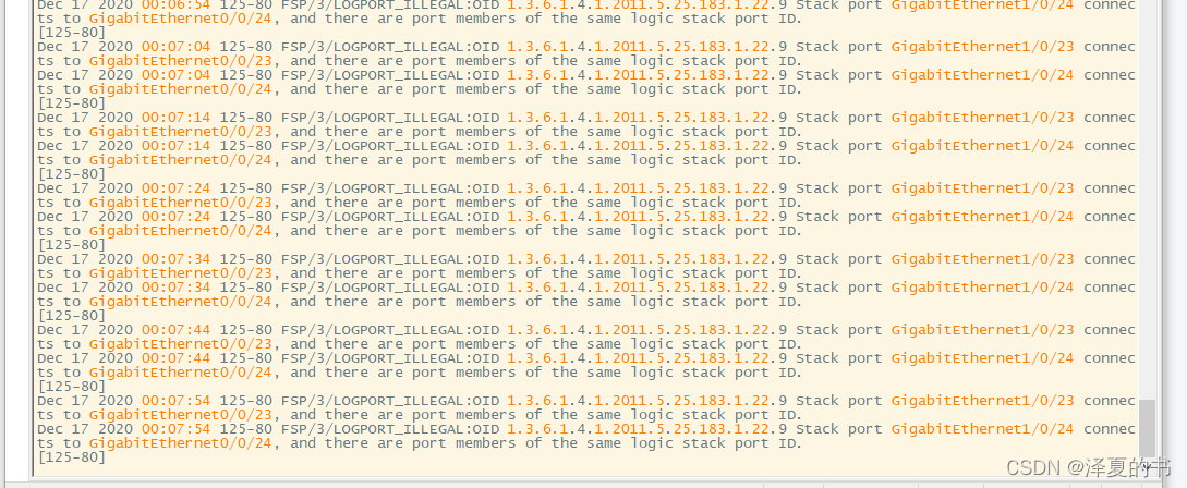
交换机一直跳这个,
逻辑堆叠端口是专用于堆叠的逻辑端口,需要和物理成员端口绑定。堆叠的每台成员交换机上支持两个逻辑堆叠端口,分别为stack-port n/1和stack-port n/2,其中n为成员交换机的堆叠ID。
注意的点:本设备的stack-port 0/1必须链接邻设备的stack-port 1/2,不然堆叠组建不成功。
SWA配置web
# 更名
[Huawei]sysname SWA# 最好先shutdown接口
[SWA]interface GigabitEthernet 0/0/23
[SWA-GigabitEthernet0/0/23]shutdown
[SWA-GigabitEthernet0/0/23]interface GigabitEthernet 0/0/24
[SWA-GigabitEthernet0/0/24]shutdown
[SWA-GigabitEthernet0/0/24]quit# SWA默认number0
[SWA]interface stack-port 0/1
[SWA-stack-port0/1]port interface GigabitEthernet 0/0/23 enable
[SWA-stack-port0/1]quit
[SWA]interface stack-port 0/2
[SWA-stack-port0/2]port  interface GigabitEthernet 0/0/24 enable
[SWA-stack-port0/2]quit# 开启23和24接口,保存配置
[SWA]interface GigabitEthernet 0/0/23
[SWA-GigabitEthernet0/0/23]undo shutdown
[SWA-GigabitEthernet0/0/23]interface GigabitEthernet 0/0/24
[SWA-GigabitEthernet0/0/24]undo shutdown
[SWA-GigabitEthernet0/0/24]quit
[SWA]quit
<SWA>save
The current configuration will be written to the device.
Are you sure to continue?[Y/N]y
Info: Please input the file name ( *.cfg, *.zip ) [vrpcfg.zip]:
Now saving the current configuration to the slot 0.
Save the configuration successfully.
SWB配置svg
# 更名
[Huawei]sysname SWB# 关闭接口
[SWB]interface GigabitEthernet 0/0/23
[SWB-GigabitEthernet0/0/23]shutdown
[SWB-GigabitEthernet0/0/23]interface GigabitEthernet 0/0/24
[SWB-GigabitEthernet0/0/24]shutdown
[SWB-GigabitEthernet0/0/24]quit# 修改为员号
[SWB]stack slot 0 renumber 1# 默认100,华为是1-255,值越大优先级越高会被推举为Master
[SWB]stack slot 0 priority 10
[SWB]interface stack-port 1/1
[SWB-stack-port0/1]port  interface GigabitEthernet 1/0/23 enable
[SWB-stack-port0/1]quit
[SWB]interface stack-port 1/2
[SWB-stack-port0/2]port interface  GigabitEthernet 1/0/24 enable
[SWB-stack-port0/2]quit# 开启23和24接口,保存配置
[SWB]interface GigabitEthernet 1/0/23
[SWB-GigabitEthernet0/0/23]undo shutdown
[SWB-GigabitEthernet0/0/23]interface GigabitEthernet 1/0/24
[SWB-GigabitEthernet0/0/24]undo shutdown
[SWB-GigabitEthernet0/0/24]quit
[SWB]quit
<SWB>sava
The current configuration will be written to the device.
Are you sure to continue?[Y/N]y
Info: Please input the file name ( *.cfg, *.zip ) [vrpcfg.zip]:
Now saving the current configuration to the slot 0.
Save the configuration successfully.
最后重启两台交换机
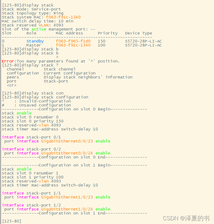
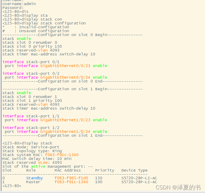
正常状况下就配置好了,重启后可查看在一台交换机上接口数量是否增长一倍测试
[SWA]display interface brief
本文来自互联网用户投稿,该文观点仅代表作者本人,不代表本站立场。本站仅提供信息存储空间服务,不拥有所有权,不承担相关法律责任。如若转载,请注明出处:http://www.taodudu.cc/news/show-5008093.html
如若内容造成侵权/违法违规/事实不符,请联系淘嘟嘟网邮箱:809451989@qq.com进行投诉反馈,一经查实,立即删除!
相关文章:
- 华为s5735交换机配置ssh远程登陆
- 华为交换机镜像简要配置说明
- Html5+Css实战前端小米官网左侧导航(思路+详解+素材)
- 图书浏览界面html代码,图书系统HTML模版
- 2020黑马旅游网项目素材及源码(无废话版)
- HTML实现取餐小票
- Html.from()加载网络图片
- 【HTML CSS】笔记4日 [ 学成在线素材 ]
- html5游戏源码素材哪家强?Top3都在这!
- 云函数uni-id微信授权登录小记
- flutter中对接微信登录
- vue2微信授权登录
- 微信登录-6问题解决方案
- Ping32文档透明加密系统
- 加密软件运用了哪些技术
- 加密软件
- mysql 加密 tde_[SQL Server] 利用透明数据加密(TDE)对整个数据库加密
- Hadoop 2.10.1 HDFS 透明加密原理 + 实战 + 验证
- Windows源代码透明加密系统软件哪个好用?2020企业数据防泄密首选
- 透明加密软件技术优势在哪
- 文件透明加密,保护重要数据的安全性
- k8s标签(label)的使用
- HTML <s> 标签
- k8s 指定节点调度标签
- s:set标签的用法
- struts2的s:password标签问题!
- s:property标签将html标签转义成amp;字符
- 让你认清楚JSP中的所有东西(java/JSP/EL/OGNL/JSTL/c标签/s标签/HTML/javascript/CSS)
- Struts2 S标签 数字格式化成金额输出
- list集合存list 以及s标签在foreach循环遍历中用EL表达式取值